MAKE NODEMC BOARD AS Wi-Fi ACCESS POINT FOR WEB SERVER
In this experiment, we will learn how to make your NodeMCU Board as an Access Point (AP-Mode) with Arduino Coding. This ESP8266 board will act as Wireless Router and the devices can connect the NodeMCU. This mode will help to create a Local Area Network between the devices it can’t push and pull the data from the cloud the Communication happens between the locally connected devices only.
Synopsis

In this experiment, we will learn how to make your NodeMCU Board as an Access Point (AP-Mode) with Arduino Coding. This ESP8266 board will act as Wireless Router and the devices can connect the NodeMCU. This mode will help to create a Local Area Network between the devices it can’t push and pull the data from the cloud the Communication happens between the locally connected devices only.

Description

ESP8266 NodeMCU V1.0 Board featured with the 2 Modes:

1. Access Point Mode (Board will act as Hotspot)

2. Station Mode (Board will act as a client to the Router)

This board consists of enough flash memory (4MB) to store the Simple Webpages and clients will access those pages through their browsers by running the Webserver at firmware Level, with the help of a web interface, you can control the devices and monitor the sensor values in which we are connected to the NodeMCU board.

NodeMCU

A NodeMCU is a development board with an inbuilt Wi-Fi module in it. It is a basic and cheapest board to carry out projects using internet of things. The NodeMCU has ESP8266 microcontroller unit in it. The operation of this microcontroller is controlled with the programs used in Arduino thus making it very easier to use and also to learn basic IoT projects. This board has inbuilt 2.4GHz antenna to receive Wi-Fi functions. This board has a memory of 4mb to store the data acting as ROM and 64Kb of RAM. This board operates at 3.3 volts and 5v and it is mandatory to operate the board at these voltage levels and if voltage is more than that it will board may damage few GPIO pins (general input-output pins).


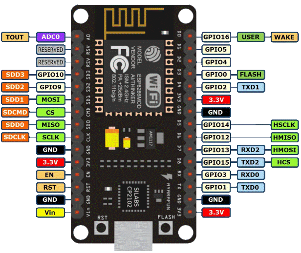
Pin Configuration of NodeMCU

1. Vin: 3.3V can be provided at this pin as the supply to power on the board. This pin is used to power on the entire microcontroller.

2. GND: This pin is connected to the negative terminal of the battery.

3. RST: This pin resets the microcontroller and clears the memory.

4. EN: This pin is used to enable the operation of microcontroller.

5. 3V3: This pin provides 3V output and this can be used to power up some sensor units connected to the microcontroller.

6. SD1, CMD, SD0, CLK: These pins are used in SPI communication, that is it is used to transfer the signals between two microcontrollers, Rx and Tx modules with asynchronous transmission.

7. SD3, SD2: These pins can also function as asynchronous transmission or as GPIO pins.

8. RSV: These are two reserved pins used by the microcontroller and cannot be used in connecting any external circuits to it.

9. A0: This microcontroller only has one analog pin for Analog communication. This A0 pin is used in analog signal communication.

10. GPIO 1 – 16: This controller board has 16 input-output pins which be used as input or output pin based on the programming.

11. GP10 1, 3, 13, 15: This microcontroller has 2 UART communication pins, RX0, TX0 (GPIO 1 & GPIO 3) and RX1, TX1 (GPIO 13, GPIO15).

Schematic


Code

#include<ESP8266WiFi.h>
#include<ESP8266WebServer.h>
ESP8266WebServer server;
//======================================
//HTML DEVICE CONTROL PAGESOURCE CODE
//=======================================
  const char MAIN_Page[]PROGMEM = R"======(
<html>
<head>
<title>Gemicates</title>
</head>
<body>
 <center> <h1>NodeMCU Webserver</h1> </center>
  <h4>Synopsis</h4>
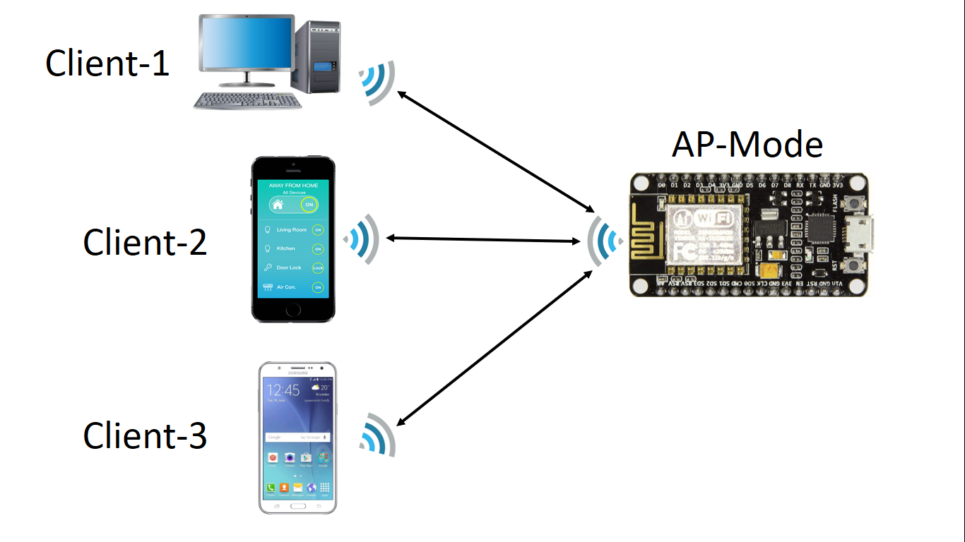
<p>In this experiment, we will learn how to make your NodeMCU Board as an Access Point (AP-Mode) with Arduino Coding. This ESP8266 board will act as Wireless Router and the devices can connect the NodeMCU. </p>
<p>This mode will help to create a Local Area Network between the devices it can’t push and pull the data from the cloud the Communication happens between the locally connected devices only.  </p>

<h4>Description</h4>
ESP8266 NodeMCU V1.0 Board featured with the 2 Modes: 
1.  Access Point Mode (Board will act as Hotspot)
2.  Station Mode (Board will act as a client to the Router)
This board consists of enough flash memory (4MB) to store the Simple Webpages and clients will access those pages through their browsers by running the Webserver at firmware Level, with the help of a web interface, you can control the devices and monitor the sensor values in which we are connected to the NodeMCU board.

<h4>Hardware Needed</h4>
<ol>
<li>NodeMCU Board</li>
<li>USB A to Micro USB Cable</li>
<li>Wi-Fi Enabled Devices like Mobile, Laptop, etc...</li>
</ol>
<h4>Software Needed</h4>
<ol>
<li>Arduino IDE</li>
</ol>

<h4>Procedure</h4>
<ol>
<li>Set the SSID (Wi-Fi-Name) and Password in the code which you preferred </li>
<li>Upload the Code into the NodeMCU through your Arduino IDE by selecting respective board models.</li>
<li>You can connect to your NodeMCU Hotspot with the proper credentials mentioned in the code.</li>
</ol>
</body>
</html>
)======";
//======================================
//SETUP FUNCTION
//=======================================
void setup()
{
  Serial.begin(9600);
  Serial.print("Enabling the Hotspot in NodeMCU..");
  boolean HOTSPOT = WiFi.softAP("NODEMCU-AP", "12345678");
  if(HOTSPOT == true)
  {
    Serial.println("HOTSPOT IS READY");
  }
  else
  {
    Serial.println("Failed! to Switch the Hotspot");
  }
  
  Serial.print("ACCESS POINT IP address: ");
  Serial.println(WiFi.softAPIP());
  Serial.print("LOCAL IP address: ");
  Serial.println(WiFi.localIP());
  server.on("/", Homepage);
  server.begin();
 }
//======================================
//LOOP FUNCTION
//=======================================
void loop() 
{
  server.handleClient();
}
//======================================
//HOME PAGE
//=======================================
void Homepage()
{
  String s = MAIN_Page;//read html content
  server.send(200,"text/html",s);//send web page
}

Error message here!

Show Error message here!


Forgot your password?

Error message here!

Send OTP

Error message here!

Show Error message here!


Lost your password? Please enter your email address. You will receive a password you Need.

Send Error message here!


Back to log-in

Close